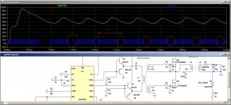
#Sg3525 ir2110 smps rarest full
The following design shows the standard module which may be integrated to any ordinary SG3525 inverter across the output pins of the IC for accomplishing a highly efficient SG3525 full bridge or H-bridge inverter circuit.
#Sg3525 ir2110 smps rarest how to
Now since we know how to implement a full bridge network using bootstrapping, let’s try to understand how this could be applied for achieving a full bridge SG3525 inverter circuit, which is by far one of the the most popular and the most sought after ICs for making an inverter. How to Make a SG3525 Full Bridge Inverter Circuit Therefore these are able to operate using the Vcc supply voltage itself and without any enhancements. The low side mosfet do not require this critical configuration simply because the source of the low side mosets are directly grounded. This crucial parameter wherein a capacitor is used for raising the gate voltage of a high-side mosfet to 10V higher than its drain supply voltage is called bootstrapping, and the circuit for accomplishing this is termed as bootstrapping network. Normally this is implemented using a fast recovery diode in conjunction with a high voltage capacitor. Once this is accomplished we can expect an optimal conduction from the high side mosfets via the low side mosfets to complete the one side cycle of the push pull frequency. If you inspect the high side mosfet in a full bridge network, you will find that the high side mosfets are actually arranged as source followers, and therefore demand a gate triggering voltage that needs to be a minimum 10V over the drain supply volts. If we interpret the above for a mosfet, we find that the gate voltage of an source follower mosfet must be at least 5V, or ideally 10V higher than the supply voltage connected at the drain side of the device. In this configuration we learned that the base voltage for the transistor must be always 0.6V higher than the emitter voltage at the collector side of the transistor, in order to enable the transistor to conduct across collector to emitter. In one of my earlier posts I comprehensively explained how emitter follower transistor works, which can be exactly applicable for a mosfet source follower circuit as well. (If you are having difficulty understanding please let me know through comments.) So basically, unless the gate/source potential of this mosfet is able to exceed the maximum value of this rising source potential by at least 12V, the mosfet won't conduct efficiently. This rising potential could be as high as the drain voltage of the high side mosfet. It's because initially the load at the source of the high side mosfet presents a high impedance, resulting in a mounting voltage at the source of the mosfet. When identical devices or 4 n-channel mosfets are used in a full bridge network, bootstrapping becomes imperative. So what’s exactly a Bootstrapping Network and how does this become so crucial while developing a Full bridge inverter circuit?

The crucial hurdle in a full bridge or a H-bridge design is the incorporation of 4 N-channel mosfet full bridge topology, which in turn demands the incorporation of a bootstrap mechanism for the high side mosfets.

#Sg3525 ir2110 smps rarest driver
Whenever we think of a full bridge or an H-bridge inverter circuit, we are able to identify circuits having specialized driver ICs which makes us wonder, isn’t it really possible to design a full bridge inverter using ordinary components?Īlthough this may look daunting, a little understanding of the concept helps us realize that after all the process may not be that complex. Why Full-Bridge Inverter Circuit is not Easy


 0 kommentar(er)
